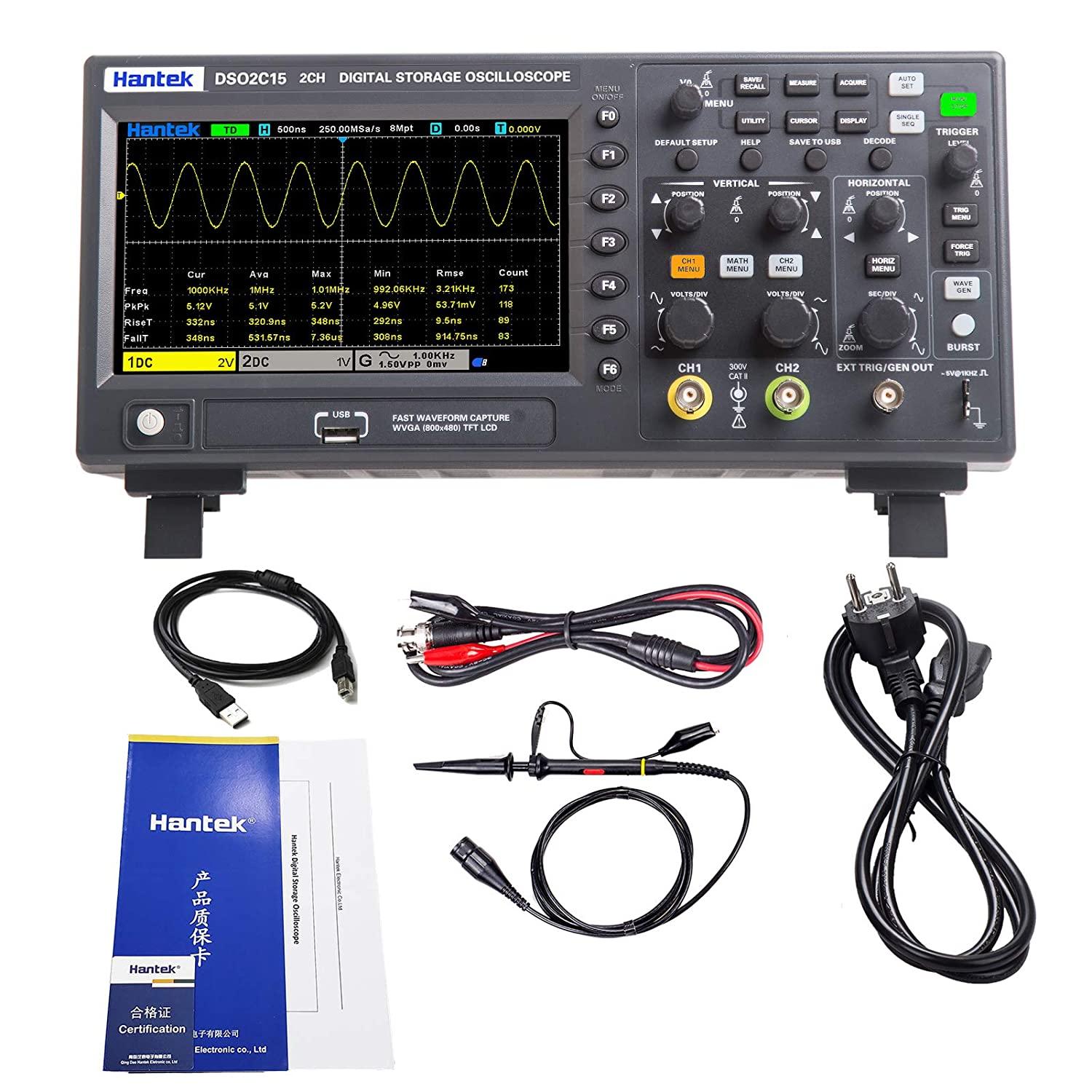
Oscilloscope Hantek Dso2c15 Channel 2 Channel 150mhz 1gsa/s Sampling Rate Economical Dual Channel Digital Storage Oscilloscope
- $78.00 / >=2 pieces
- 2 pieces
- Shenzhen Robotlinking Technology Co., Ltd.
- Guangdong, China
- Ms Moira Lin
PRODUCT DETAIL
| color: | Black | Packaging details: | Original carton, anti-static plastic bag |
| pack: | standard meal | brand: | robot linkage,robot linkage |
| thing: | DSO2C15 digital storage oscilloscope | Warranty: | 3 years |
| Place of origin: | Guangdong, China | model: | IC078 |
| port: | Shenzhen Hong Kong | payment terms: | Western Union, T/T, Alibaba Trade/WeChat/Alipay/Paypal/Bank Transfer |
| Health status: | 100% brand | channel: | 2 |
| Customization support: | original design manufacturer | type: | oscilloscope,oscilloscope |
| Supply capacity: | 10,000 pieces per month | bandwidth: | 150 MHz |
| product name: | Hantek DSO2C15 digital storage oscilloscope | plug: | us |

Contact us for cheaper shipping
Product Description
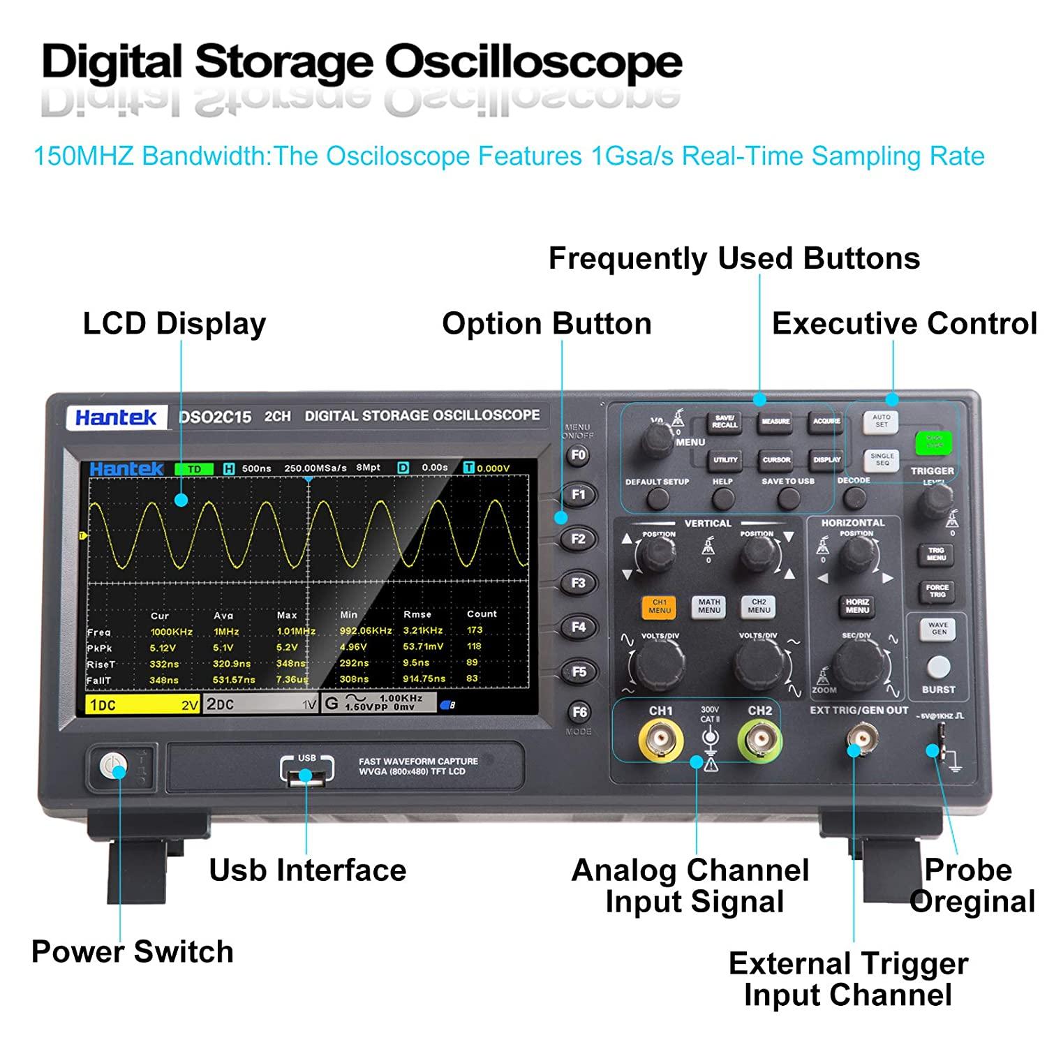
Hantek Dso2c15 oscilloscope 2ch channel 150mhz 1gsa/s sampling rate dual channel digital economical storage oscilloscope
1) 2 channels, each controlled by independent knobs;
2) 150MHZ, analog channel bandwidth;
3) 1 GSa/s real-time sampling rate;
4) 8M storage depth;
5) Vertical range 2mV/div~10V/div;
6) Vertical resolution: 8bit;
7) Trigger: edge, pulse width, video, slope, timeout, window, pattern, interval, delay, UART, LIN, CAN, SPI, IIC;
8) CAN decoding and protocol analysis: RS232/UART, I2C, SPI, CAN, LIN
9) Can be saved as settings, waveforms, reference waveforms, CSV, pictures and other data formats;
10) 5-digit digital voltmeter and 6-digit hardware frequency indication function;
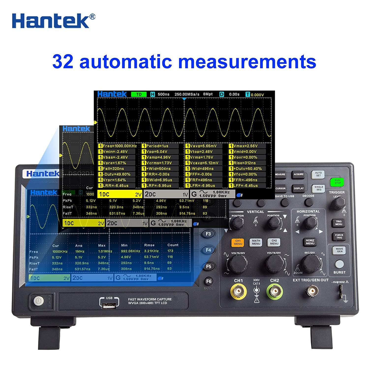
11) 32 types of automatic measurement and statistics, real-time statistics of maximum value, minimum value, standard deviation, etc.;
12) 2 sets of digital voltmeters;
13) Support threshold testing and free measurement within the screen;
14) Rich SCPI remote command control;
15) Various external interfaces: USB Host/Device.
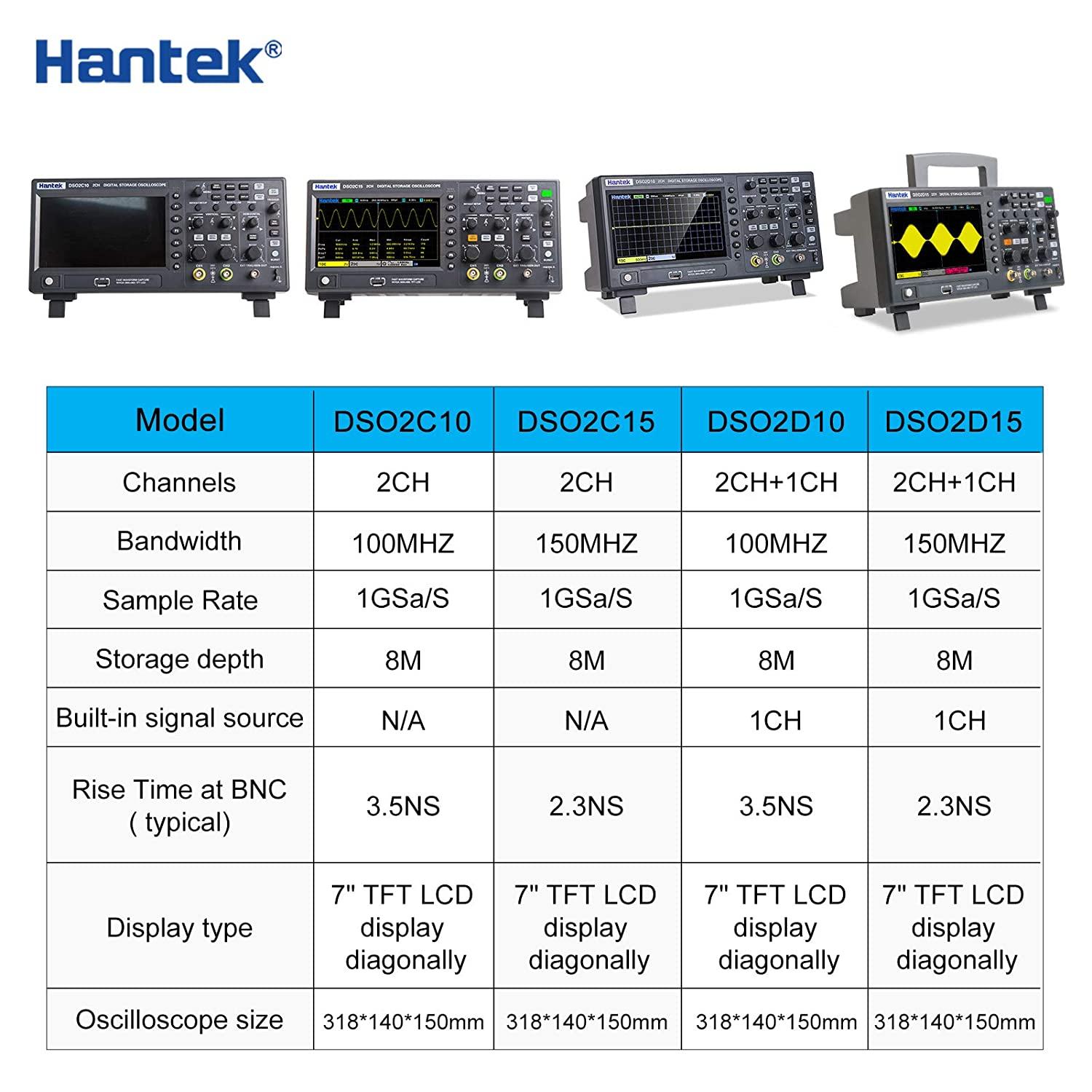
Model | DSO2D15 | DSO2D10 | DSO2C15 | DSO2C10 | ||||
bandwidth | 150 MHz | 100 MHz | 150 MHz | 100 MHz | ||||
Oscilloscope channel | 2 channels | 2 channels | 2 channels | 2 channels | ||||
waveform generator | 1 way | 1 way | - | - | ||||
Oscilloscope | ||||||||
Sampling Rate | 1GSa/s (single channel) 500MSa/s (two channels) | |||||||
get | ||||||||
normal | sample | |||||||
peak to peak | Shows high frequency and random glitches | |||||||
Average | Average waveform, times: 4, 8, 16, 32, 64, 128 | |||||||
high resolution | up to 12 bits | |||||||
enter | ||||||||
Input coupling | DC, AC, ground | |||||||
input resistance | 1MΩ±2% ‖20pF±3pF | |||||||
Probe attenuation coefficient | 1X, 10X, 100X, 1000X | |||||||
Rated voltage | 300VCATII | |||||||
Maximum input voltage | 300VRMS (10X) | |||||||
horizontal | ||||||||
Waveform interpolation | (sin x)/x | |||||||
Maximum record length | Maximum single channel 8M | |||||||
Maximum 4M for two channels | ||||||||
Horizontal scale range | 2ns/div~100s/div 1, 2, 5 steps | |||||||
time base mode | YT, XY, scroll | |||||||
zero offset | ±0.5 div×minimum hour base gear | |||||||
Sample rate and delay time accuracy | ±25ppm | |||||||
Delta time measurement accuracy (full bandwidth) sample rate and delay time accuracy | Single, normal mode ± (1 sampling interval + 100ppm × reading + 0.6ns) | |||||||
>16 times average value±(1 sampling interval+100ppm×reading+0.4ns) | ||||||||
Sampling interval=second/division÷200 | ||||||||
Sample rate and delay time accuracy | ±50ppm (any interval greater than 1ms) | |||||||
vertical | ||||||||
Model | DSO2D15 | DSO2D10 | DSO2C15 | DSO2C10 | ||||
bandwidth | 150 MHz | 100 MHz | 150 MHz | 100 MHz | ||||
BNC position rise time (typ) | 2.4 nanoseconds | 3.5 nanoseconds | 2.4 nanoseconds | 3.5 nanoseconds | ||||
vertical resolution | 8-bit resolution, each channel sampled simultaneously | |||||||
vertical sensitivity | 2mV/div to 10V/div | |||||||
Offset range | ≥200mV/div, ±1V; | |||||||
<200mV/div±50V | ||||||||
computation | +, -, ×, ÷, FFT | |||||||
Fast Fourier Transform | Windows: Rectangular, Hanning, Hamming, Blackman, Bartlett, Flat Top | |||||||
bandwidth limit | 20MHz | |||||||
Bass response (-3db) | At BNC position ≤ 10Hz | |||||||
Vertical gain accuracy | In "normal" or "average" acquisition mode, the accuracy is ±3% from 10V/div to 10mV/div; | |||||||
±4% accuracy from 5mV/div to 2mV/div in Normal or Average acquisition mode | ||||||||
NOTE: Bandwidth is reduced to 6MHz when using 1X probe | ||||||||
trigger | ||||||||
Trigger type | Edge, pulse width, video, slope, timeout, window, mode, interval, underamp, UART, LIN, CAN, SPI, IIC | |||||||
Trigger level range | ±5 blocks from the center of the screen | |||||||
Trigger mode | Automatic, normal, single | |||||||
grade | CH1~CH2 | ±4 divisions from the center of the screen | ||||||
external | 0~3.3V | |||||||
Release range | 8 nanoseconds~10 seconds | |||||||
Trigger level accuracy | CH1~CH2 | Within ±4 divisions from the center of the screen is 0.2 divisions × volts/div. | ||||||
external | ±(set value×6%+40mV) | |||||||
edge triggered | slope | rising edge, falling edge, rising edge or falling edge | ||||||
signal source | CH1, CH2, external | |||||||
Pulse width trigger | polarity | Positive polarity, negative polarity | ||||||
Condition (when) | <,>,!=,= | |||||||
signal source | CH1~CH2, | |||||||
Pulse width range | 8 nanoseconds~10 seconds | |||||||
accuracy | 8 nanoseconds | |||||||
video trigger | Signal standard | NTSC, PAL | ||||||
signal source | CH1~CH2 | |||||||
Synchronize | Scan line number, line number, odd field, even field, full field | |||||||
Ramp trigger | slope | Rise and fall | ||||||
Condition (when) | <,>,!=,= | |||||||
signal source | Channel 1 ~ Channel 2 | |||||||
time limit | 8 nanoseconds~10 seconds | |||||||
accuracy | 8 nanoseconds | |||||||
Overtime trigger | signal source | CH1~CH2, | ||||||
polarity | Positive polarity, negative polarity | |||||||
time limit | 8 nanoseconds~10 seconds | |||||||
accuracy | 8 nanoseconds | |||||||
window trigger | signal source | CH1~CH2 | ||||||
pattern trigger | pattern | 0: low level; 1: high level; X: ignore | ||||||
Level (signal source) | CH1~CH2 | |||||||
interval trigger | slope | Rise and fall | ||||||
Condition (when) | <,>,!=,= | |||||||
signal source | CH1~CH2 | |||||||
time limit | 8 nanoseconds~10 seconds | |||||||
accuracy | 8 nanoseconds | |||||||
Under amplifier trigger | polarity | Positive polarity, negative polarity | ||||||
Condition (when) | <,>,!=,= | |||||||
signal source | CH1~CH2 | |||||||
time limit | 8 nanoseconds~10 seconds | |||||||
accuracy | 8 nanoseconds | |||||||
Serial trigger | Condition (when) | Start, Stop, Data, Parity ERR, COM ERR | ||||||
Signal source (RX/TX) | CH1~CH2 | |||||||
Data Format | Hex (hexadecimal) | |||||||
Data length | 1 byte | |||||||
Data bit width | 5 digits, 6 digits, 7 digits, 8 digits | |||||||
parity check | None, odd number, even number | |||||||
idle level | High in front and low in back | |||||||
Baud rate (optional) | 110/300/600/1200/2400/4800/9600/14400/19200/38400/57600/115200/230400/380400/460400 bits/second | |||||||
Baud rate (user-defined) | 300bit/s~334000bit/s | |||||||
LIN flip-flop | Condition (when) | Interval field, synchronization field, ID field, synchronization error, identifier, ID and data | ||||||
signal source | CH1~CH2 | |||||||
Data Format | Hex (hexadecimal) | |||||||
Baud rate (optional) | 110/300/600/1200/2400/4800/9600/14400/19200/38400/57600/115200/230400/380400/460400 bits/second | |||||||
Baud rate (user-defined) | 300bit/s~334000bit/s | |||||||
CAN trigger | Condition (when) | Start bit, remote frame ID, data frame ID, frame ID, data frame data, error frame, all errors, ACK error, overload frame | ||||||
signal source | CH1~CH2 | |||||||
Data Format | Hex (hexadecimal) | |||||||
Baud rate (optional) | 10000, 20000, 33300, 500000, 62500, 83300, 100000, 125000, 250000, 500000, 800000, 1000000 | |||||||
Baud rate (user-defined) | 5kbit/s~1Mbit/s | |||||||
SPI trigger | signal source | CH1~CH2 | ||||||
Data Format | Hex (hexadecimal) | |||||||
Data bit width | 4, 8, 16, 24, 32 | |||||||
IIC trigger | Signal source (SDA/SCL) | CH1~CH2 | ||||||
Data Format | Hex (hexadecimal) | |||||||
Data index | 0~7 | |||||||
When (condition) | Start Bit, Stop Bit, No Ack, Address, Restart, Address and Data | |||||||
Measurement | ||||||||
cursor | Voltage difference between cursors △V | |||||||
Time difference between cursors △T | ||||||||
The reciprocal of △T in Hertz (1/△T) | ||||||||
Automatic measurement | frequency, period, average, peak-to-peak, RMS, min, mixmum, rise time, fall time, +width, -width, base, top, middle, Amplitude, overshoot, preshoot, rising edge phase difference, falling edge phase difference, +duty cycle, -duty cycle, period average, PRMS, FOVshoot, ROVshoot, BWIDTH, FRF, FFR, LRR, LRF, LFR, LFF | |||||||
digital virtual machine | data source | Channel 1, Channel 2 | ||||||
Measurement type | DC effective value | |||||||
Exchange effective value | ||||||||
DC | ||||||||
frequency meter | Hardware 6-digit frequency meter | |||||||
arbitrary waveform generator | ||||||||
channel | 1 | |||||||
Sampling Rate | 200MSa/second | |||||||
vertical resolution | 12 bits | |||||||
maximum frequency | 25 MHz | |||||||
Standard waveform | Sine wave, square wave, ramp wave, Exp, noise, DC | |||||||
arbitrary waveform | Arb1, Arb2, Arb3, Arb4 | |||||||
crime | Frequency Range | 0.1Hz~25MHz | ||||||
Square wave/pulse | Frequency Range | 0.1Hz~10MHz | ||||||
triangle wave | Frequency Range | 0.1Hz~1MHz | ||||||
sample wave | Frequency Range | 0.1Hz~1MHz | ||||||
index | Frequency Range | 0.1Hz~5MHz | ||||||
noise | ||||||||
Arbitrary waveform 1 | Frequency Range | 0.1 Hz to 10 MHz | ||||||
Arbitrary waveform 2 | Frequency Range | 0.1 Hz to 10 MHz | ||||||
Arbitrary waveform 3 | Frequency Range | 0.1 Hz to 10 MHz | ||||||
Arbitrary waveform 4 | Frequency Range | 0.1 Hz to 10 MHz | ||||||
Waveform length | 8KSa | |||||||
frequency | accuracy | 100 ppm (<10 kHz) 50 ppm (>10 kHz) | ||||||
solve | 0.1 Hz or 4 bits, whichever is greater | |||||||
amplitude | Output range | 10mV~7Vp-p (high impedance) | ||||||
5mV~3.5Vp-p (50Ω) | ||||||||
DC bias | scope | ±3.5V, high impedance | ||||||
±1.75V, 50Ω | ||||||||
solve | 100 μV or 3 digits, whichever is greater | |||||||
accuracy | 2% (1kHz) | |||||||
Output impedance | 50 ohms | |||||||
General specifications | ||||||||
exhibit | display type | 7-inch diagonal TFT LCD | ||||||
display resolution | 800 (horizontal) * 480 (vertical) pixels | |||||||
Display color | 16 million colors (24-bit true color) | |||||||
duration | Minimum, 1 second, 5 seconds, 10 seconds, 30 seconds, infinite | |||||||
display type | point, vector | |||||||
Display brightness | adjustable | |||||||
grid type | adjustable | |||||||
grid brightness | adjustable | |||||||
interface | Standard interface | USB host, USB device | ||||||
General specifications | Probe compensator output | |||||||
Output voltage, typical | About 2Vpp input ≥1MΩ load | |||||||
Frequency, typical | 1kHz | |||||||
power supply | 100-120VACRMS(±10%), 45Hz to 440Hz, CATⅡ | |||||||
120-240VACRMS(±10%), 45Hz to 66Hz, CATⅡ | ||||||||
energy consumption | <30W | |||||||
fuse | T type, 3.15A, 250V, 5x20mm | |||||||
Operating temperature | 0~50°C (32~122°F) | |||||||
Storage temperature | -40~+71°C (-40~159.8°F) | |||||||
humidity | ≤+104°F(≤+40°C): ≤90% relative humidity | |||||||
106°C~122°C (+41°C~50°C): ≤60% relative humidity | ||||||||
high | Business and non-business | 3,000 meters (10,000 feet) | ||||||
mechanical shock | random vibration | 50Hz to 500Hz 0.31 g RMS, | ||||||
10 minutes per axis | ||||||||
non-operational | 5Hz to 500Hz 2.46g RMS, | |||||||
10 minutes per axis | ||||||||
operate | 50g, 11ms, half sine wave | |||||||
Mechanical | size | 318×110×150mm (length×width×height) | ||||||
weight | 2900g | |||||||
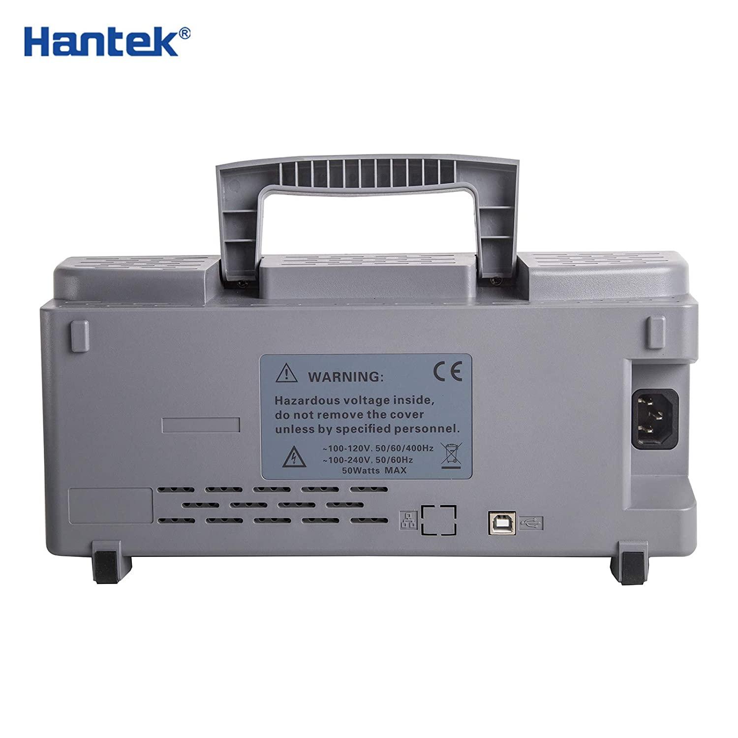
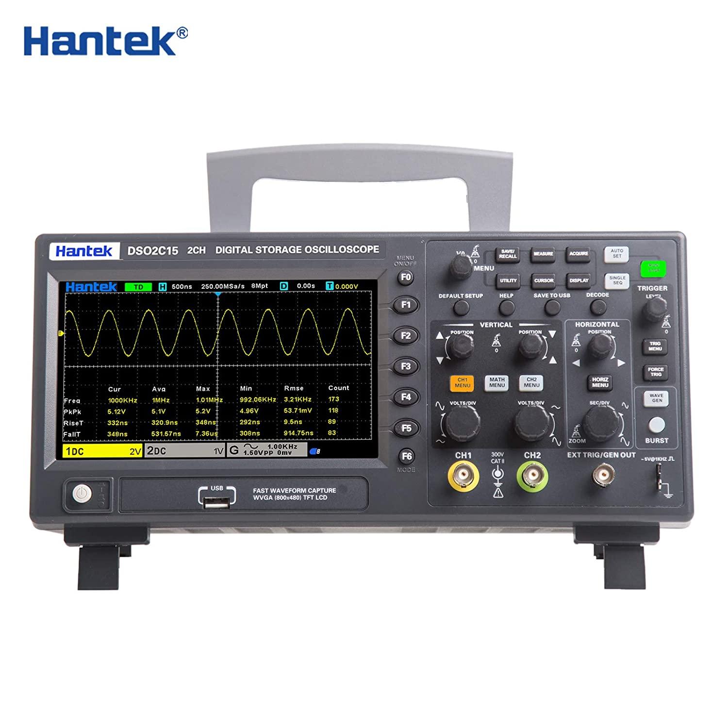
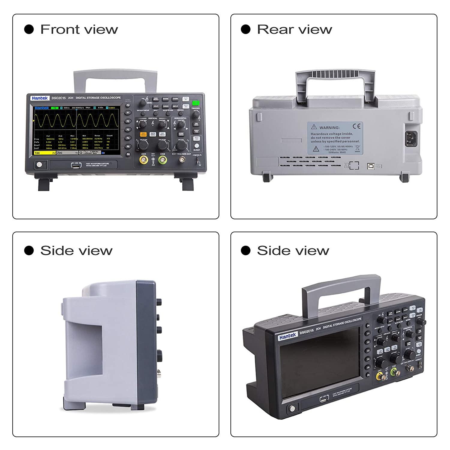
VIEW MORE
YOU MAY LIKE


